ApolloBVM - Emergency Use Ventilator |


PLEASE NOTE: This webpage will NO LONGER be updated. There is no support for these files and plans.
PLEASE NOTE: If you choose to build this or something similar, please consult with physicians, technicians and/or clinicians.
PLEASE NOTE: We are getting some AMAZING feedback. Some Frequently Asked Questions are now posted below.
Thank you so much for all of your interest. It takes a village!
DIY Instructions and Files
| The ApolloBVM is a controllable, automated add-on solution to the existing and widely available Bag Valve Mask (BVM). The device compresses the BVM with a mechanical system that is able to provide consistent and accurate ventilation with positive-pressure. This solution exists within the top range of high-acuity limited-operability (HALO) ventilator solutions with an a priori design to produce volume and pressure cycled ventilation that includes positive end-expiratory pressure (PEEP) and enriched oxygen sources. The ApolloBVM is a rapidly scalable solution with a clinician-informed end-to-end design that repurposes the existing BVM global inventory toward widespread and safe access of hospital-grade mechanical ventilation. |
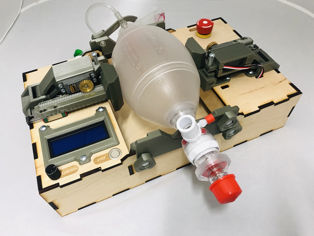
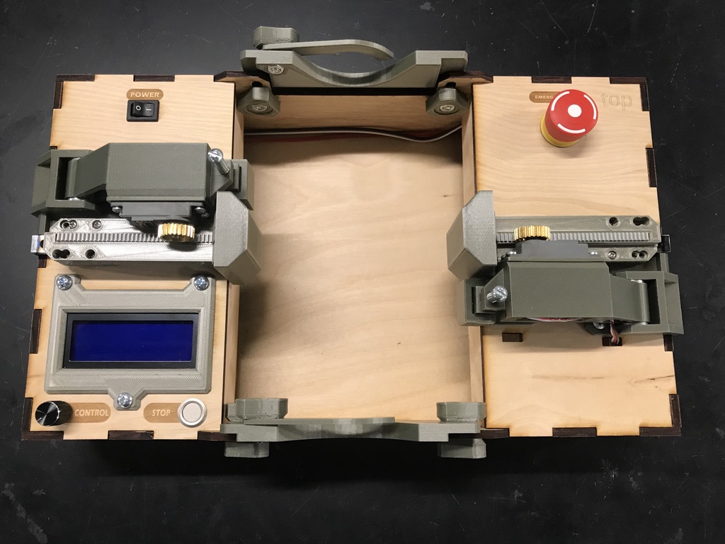
ApolloBVM Initial Prototype | ApolloBVM Acrylic Version 1 |
Skills
Assembly of the ApolloBVM should be possible with an intermediate to advanced machine assembly skill level. Operation of the device can be completed with intermediate expertise using the proper documentation, instructions, and files. Repair and maintenance of the ApolloBVM would be possible using this same documentation. Advanced knowledge would be required to access motion control and code framework to make gross modifications to the core functionality of the device.
_2020-Apr-04_08-45-31PM-000_CustomizedView11276532177_jpg.jpg) ApolloBVM Version 0 | 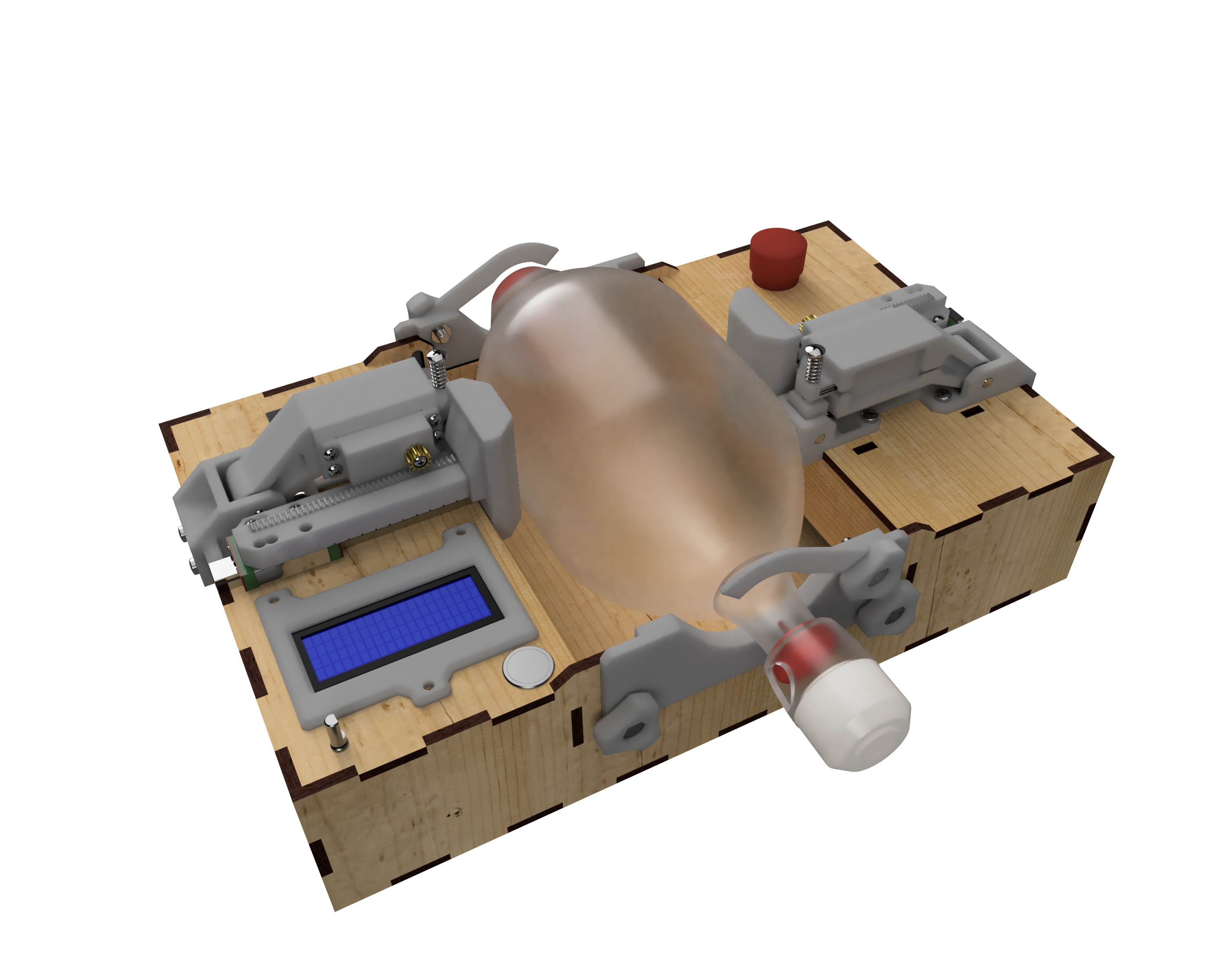 ApolloBVM Version 1 |
Parts BOM
- Motors (2x) - goBILDA 2000 Series Dual Mode Servo (2000-0025-0002)
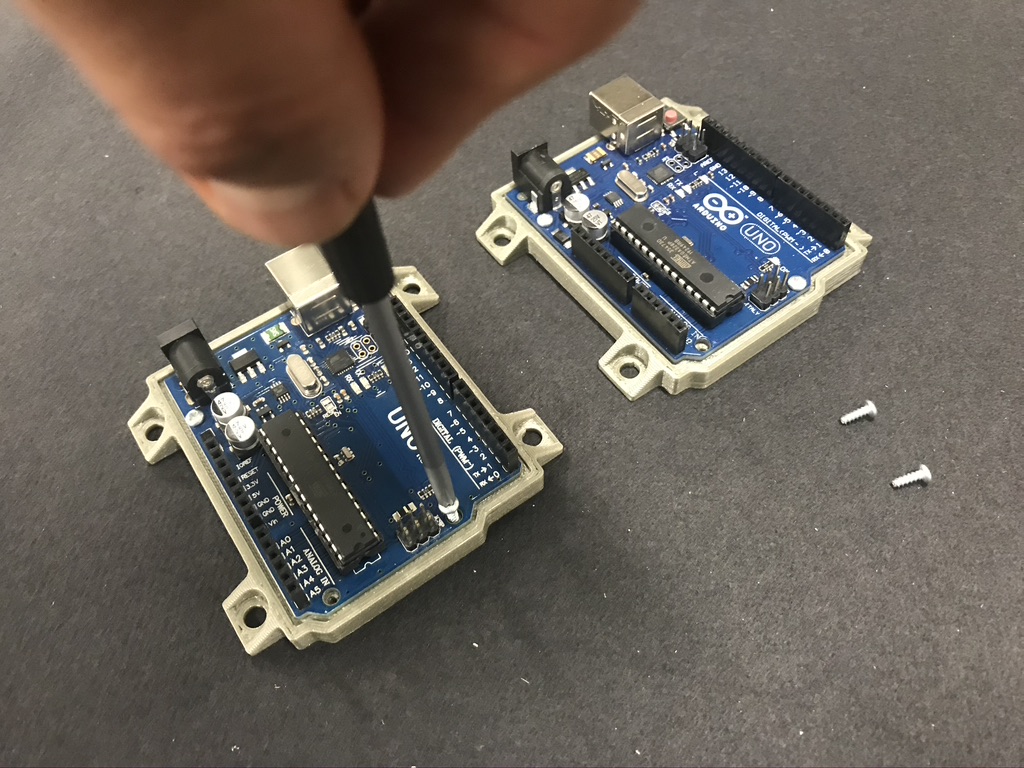
Servo City goBilda - Arduino (2x) - Arduino Uno (A000066)
Amazon AdaFruit - Wires - 22 AWG
- Power Supply - 7.5V (Model #vBK-UA-36)
Amazon - Linear Gear (2x) - 20 Degree Pressure Angle Gear Rack, 32 Pitch (2662N53)
McMaster - Gear (2x) - 32P, H23T Output Spline Servo Mount Gears (Metal) 32 Tooth (sku#615310)
Servo City - Linear Bearing Rail with slider (2x) - MGN12 - 120mm (or longer but cut to 120mm)
Aliaba Robot Digg - 1/4” Shaft (2x) - Dowel Pin, 1/4"x1" Long (98381A542)
McMaster - 1/4” Shaft (2x) - Dowel Pin, 1/4"x1-1/2" Long (98381A546)
McMaster - Spring (2x) - (P12-C029M16SQ64)
McMaster - Gear Tension Screw (2x) #10-24 x 1.5"
McMaster - Fasteners (36x) and washers (8x)
- Panel Mount 2.1mm DC barrel jack
Mouser AdaFruit - Digital Screen - Serial 20x4 Liquid Crystal Display Module
Mouser - Metal Buttons (1x) - Push Button with 360 Degree Rotary Encoder (Part#WYTP23) (KY-040 Rotary Encoder)
Amazon Bangood - Push Button (1x) (3-109-081)
Mouser - Emergency Stop Button (84-5020.0020)
Mouser - Rocker Switch (RA11131121)
Mouser - PLA Filament
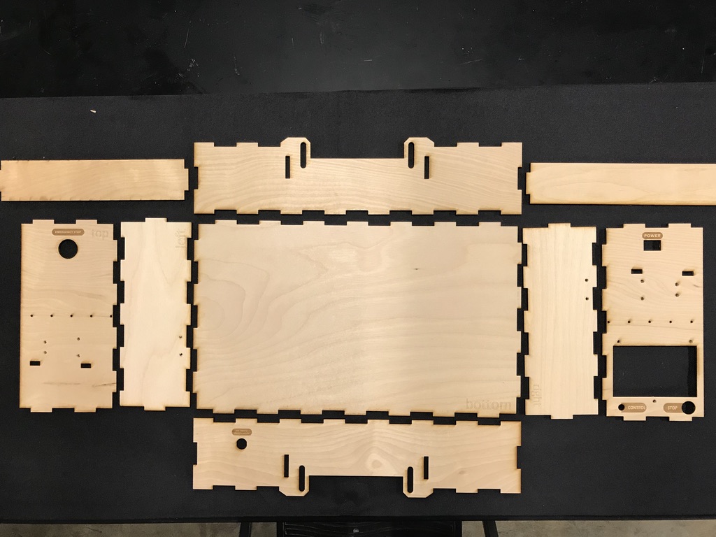
Prusament - 1/4 Birch Ply Sheet or plastic
- BVM with PEEP - AMBU Spur II
Ambu - ET endotracheal tube
Fasteners and Washers
| Item Description | Size | Quantity | McMaster-Carr P/N | LINK |
| Servo Mount Screws | #6 - ½” | 8 | 90380A148 | https://www.mcmaster.com/90380a148 |
| Linear Rail Screws | #8 - ⅜” | 10 | 90380A192 | https://www.mcmaster.com/90380a192 |
| Linear Bearing Screws* | M3 - 0.5 X 12mm | 8 | 92005A122 | https://www.mcmaster.com/92000a118 |
| Gear Screws | Note: comes with Servo motor | 2 | ||
| Motor Mount Washers | ¼” flat washer | 4 | 92141A029 | https://www.mcmaster.com/92141a029 |
| Motor Mount Screws** | #10 - 1” | 14 | 90380A240 | https://www.mcmaster.com/94060a247 |
| BVM Hold Down Nuts | ¼”-20 hex nut | 6 | 95462A029 | https://www.mcmaster.com/95462a029 |
| BVM Hold Down Screws | ¼” - 20 x 1” hex head cap screws | 6 | 92865A542 | https://www.mcmaster.com/92865a542 |
| Screen Mount Screws | #2 - 1/4" | 4 | 90380A005 | https://www.mcmaster.com/90380a005 |
| Screen Mount Screws | #10 - 1" | 3 | 90380A251 | https://www.mcmaster.com/94060a247 |
| Spring Tension Screw | 10-32 x 1-1/2" | 2 | 92196A277 | https://www.mcmaster.com/92196a277 |
| Spring Base Nut | 10-32 hex nut | 2 | 90480A195 | https://www.mcmaster.com/90480a195 |
*Note: Changed screw size from M2 to M3
**Note: Changed screw size from #10-14 x 3/4 to #10-1"
|
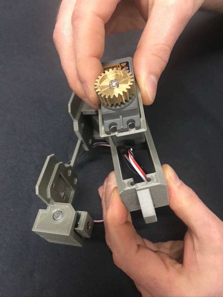
| The motor mounts is mostly 3D printed parts. Each side consists of five 3D printed parts which will be put together with fasteners and dowels. The motor should easily fit into the motor mount. Motor assembly is below. You will need to make 2 of these for the finished design. |


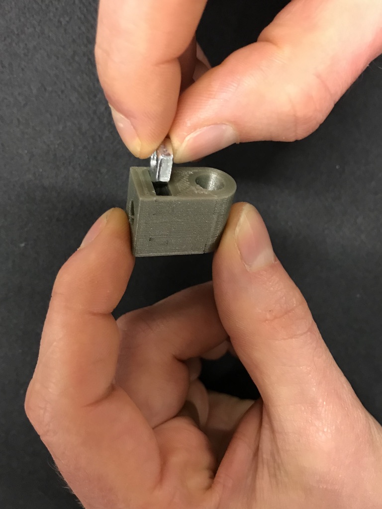
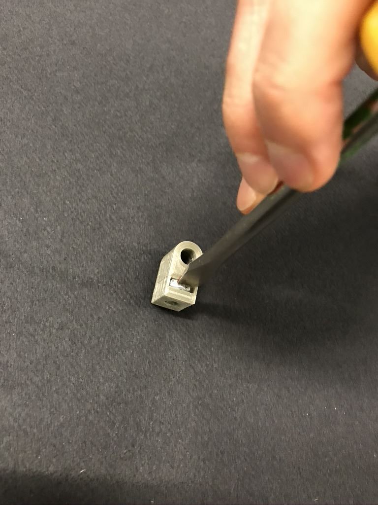
Insert (1) 10-24 nut into slot of spring base. |
Press nut until firmly seated. |
Verify nut and spring base are concentric. |

Use 1" steel dowel to attach spring base to servo mount base. |
Dowel position |
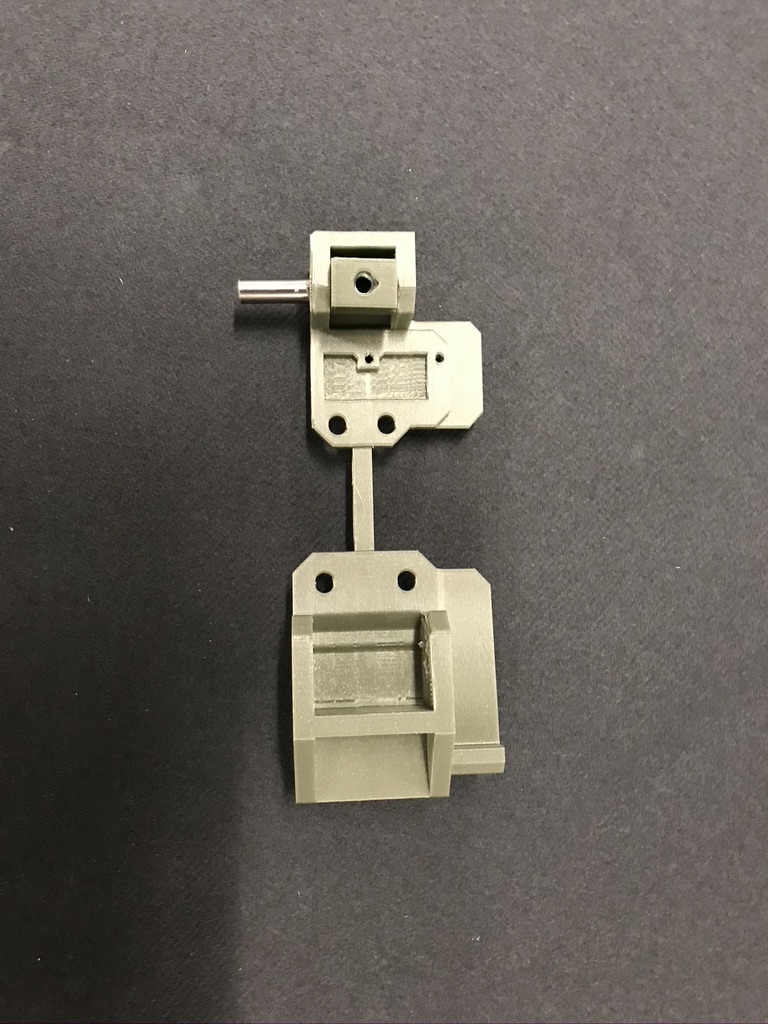
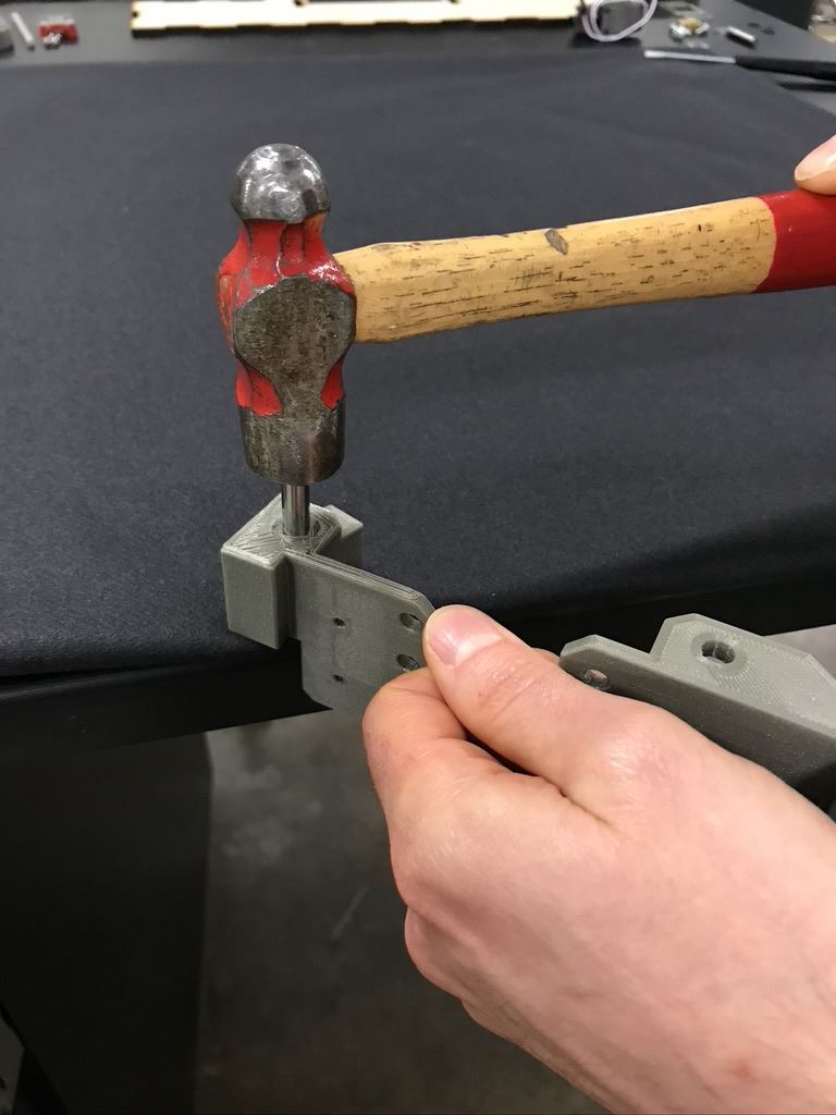
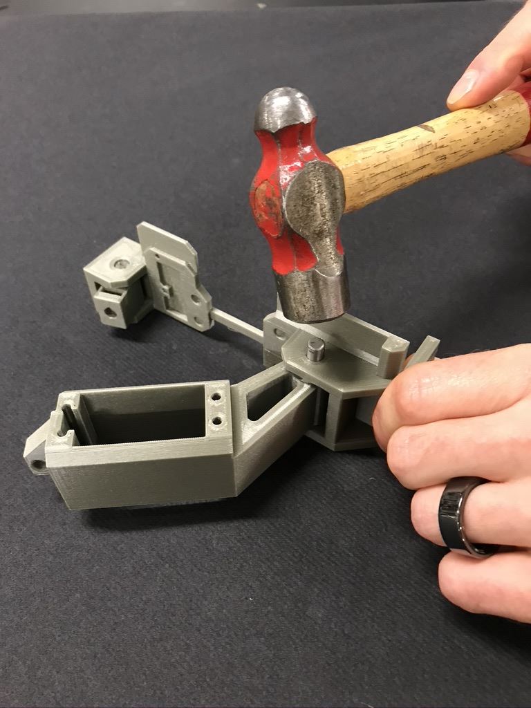
Hammer steel dowel until flush with base. |
Dowel positioned |
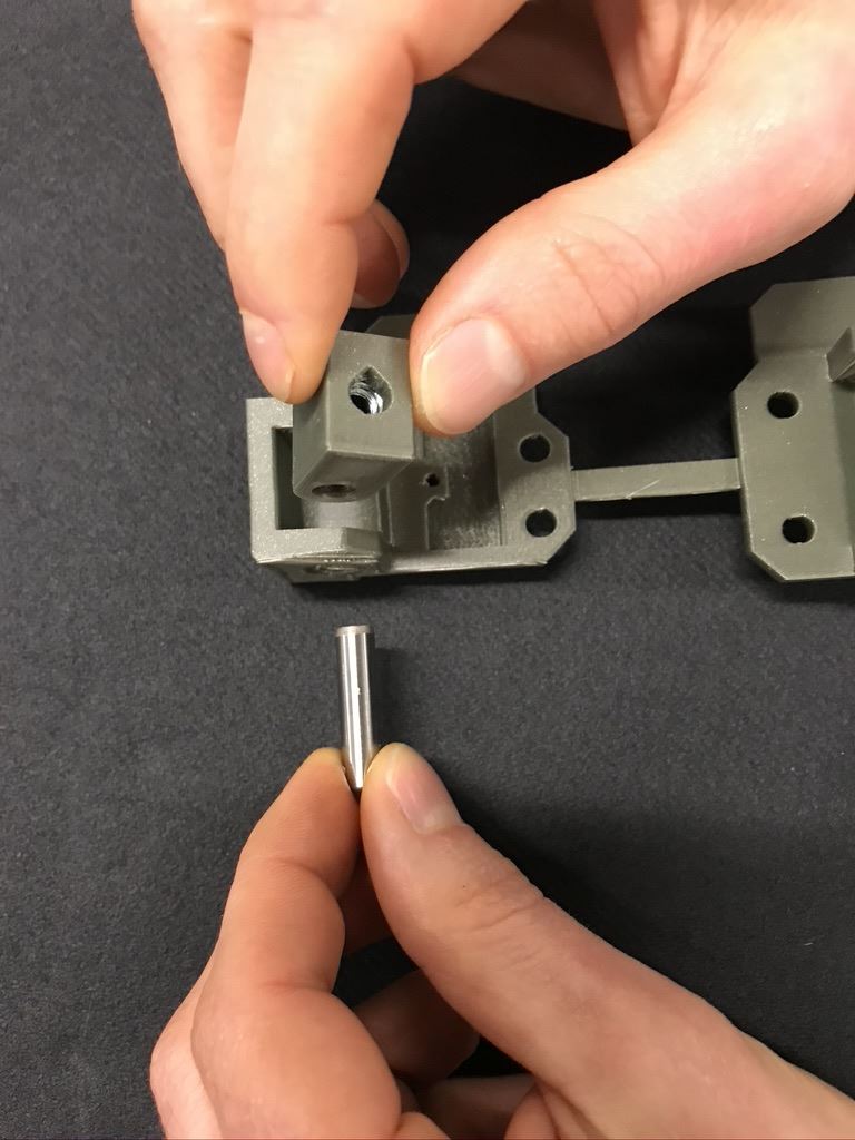
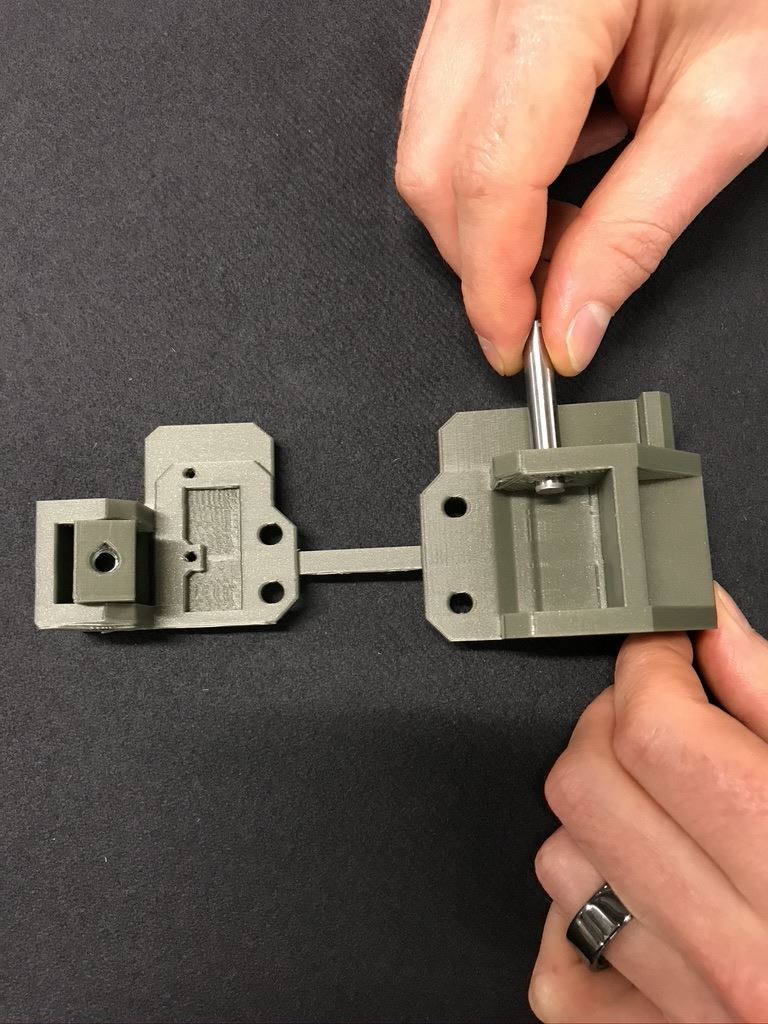
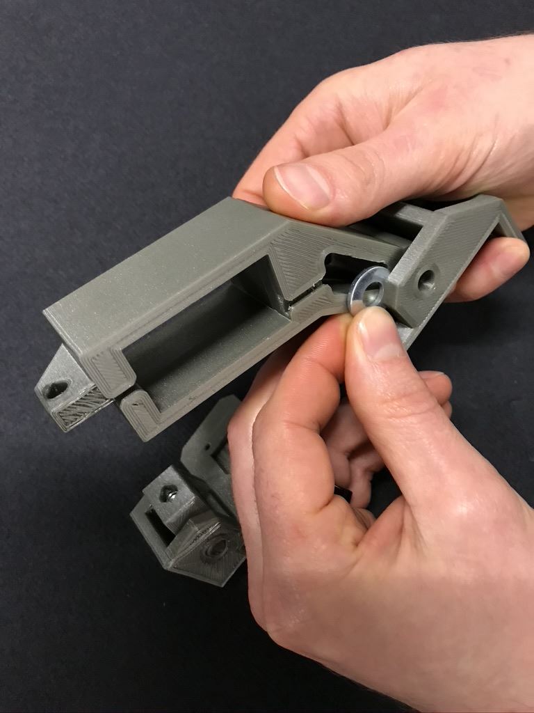
Insert 1-1/2" steel dowel enough to place 1/4" washer on tip. |
Place 1/4" washer on tip of steel dowel. |
Position servo rotational mount on steel dowel and insert dowel further, but not all the way. |
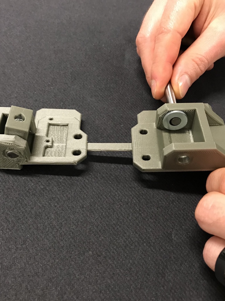

Insert 1/4" washer between base and servo rotational mount. |
Ensure washer lines up with steel dowel. |
Hammer steel dowel flush with base. |
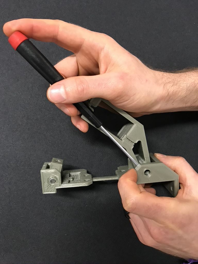
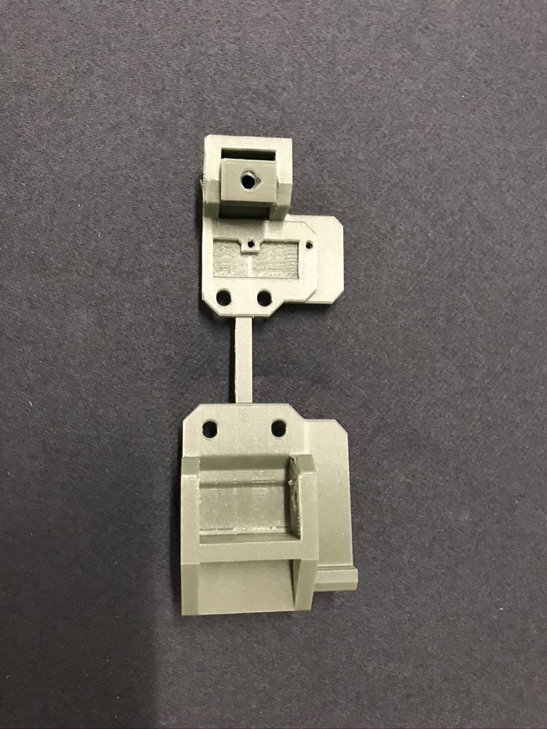
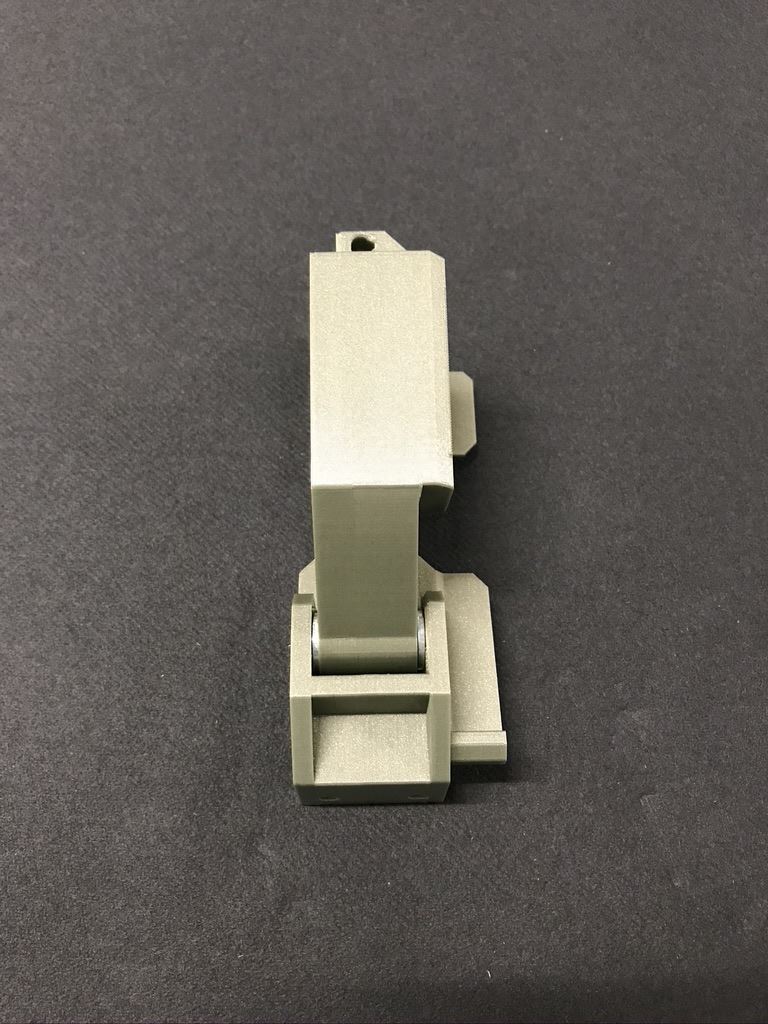
Completed motor mount assembly - side view. |
Completed motor mount assembly - back view. |
|
|
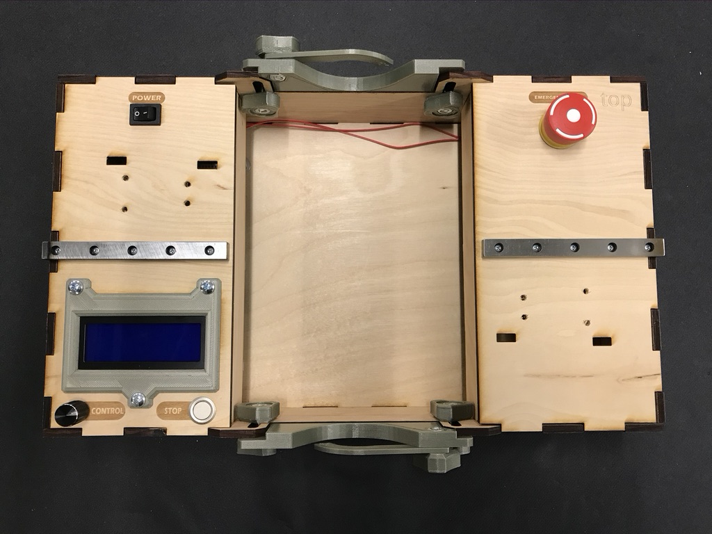
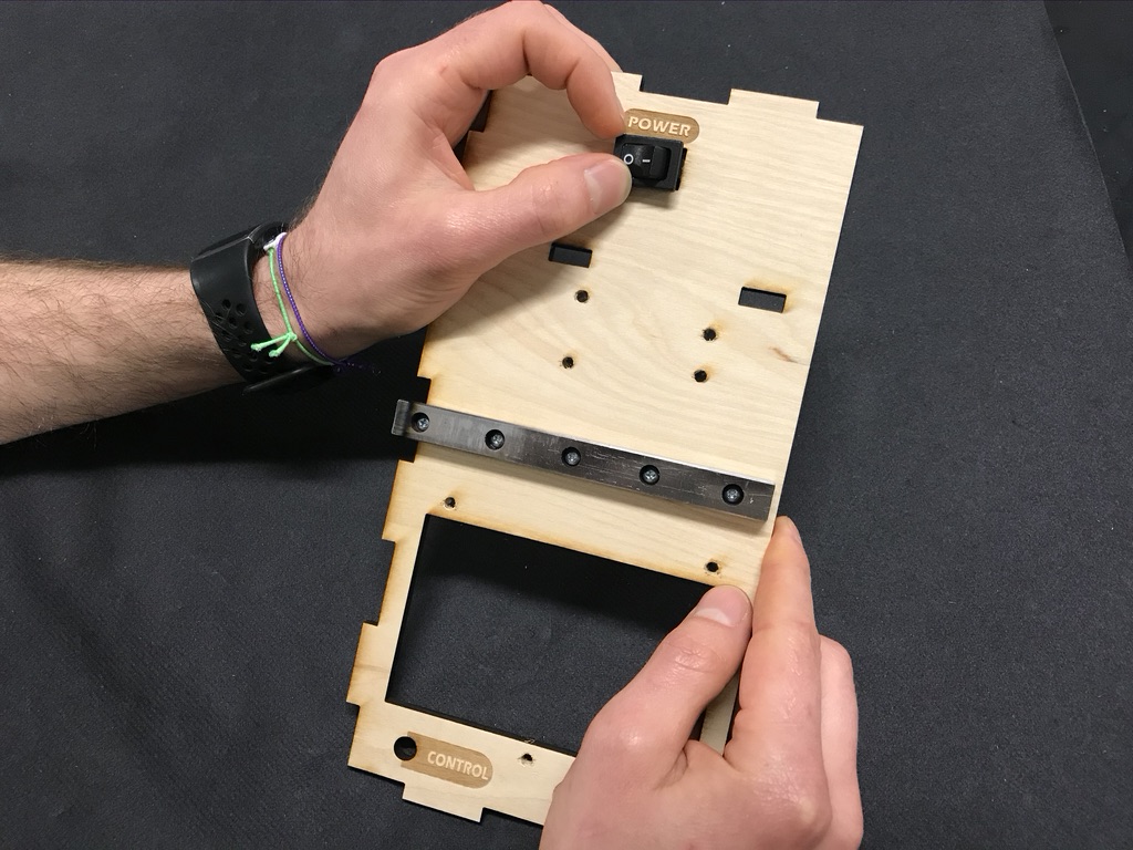
Install 120mm linear bearing rail to top panel using (5) #6 x 3/4" thread-forming screws for plastic. |
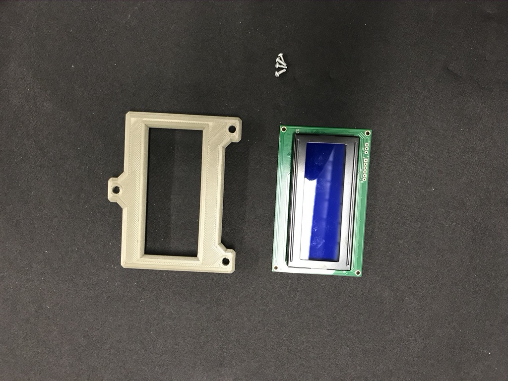
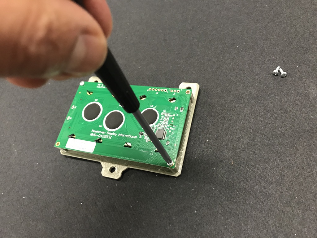
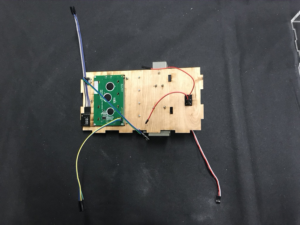
Display assembly. |
Secure 20x4 LCD display to display mount using (4) #2 x 1/4" thread-forming screws for plastic. (Note: the two screw holes on display mount is the up position) |

Press in power button with leads soldered. |
|
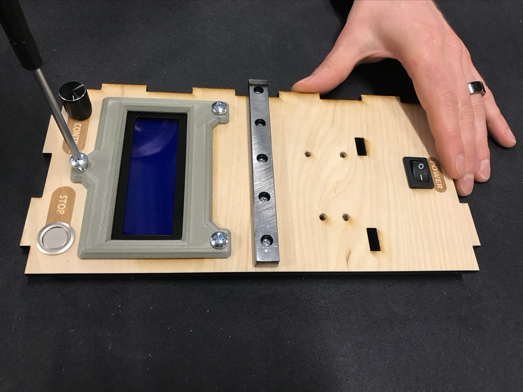
Install and secure momentary metal push button. |
Place display assembly on wood box top control panel |


Secure with (3) #8 x 3/4" self-tapping screw. |
Install and secure emergency stop button with a minimum of 16" jumper wires soldered to terminals. |
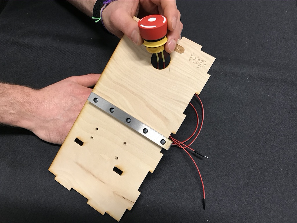
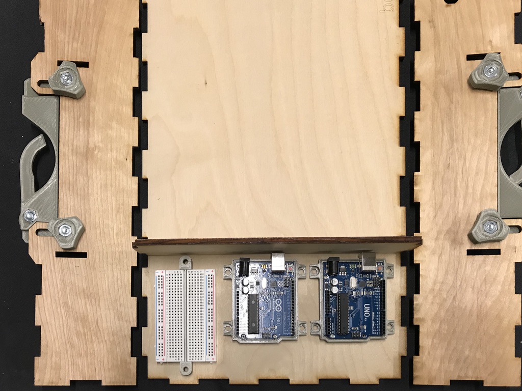
Position arduinos and bread board inside box as shown. |
Mark holes and outline mounts. |
Attach mounts with hot glue. |
Using wood glue, assemble the bottom, sides, and braces. |


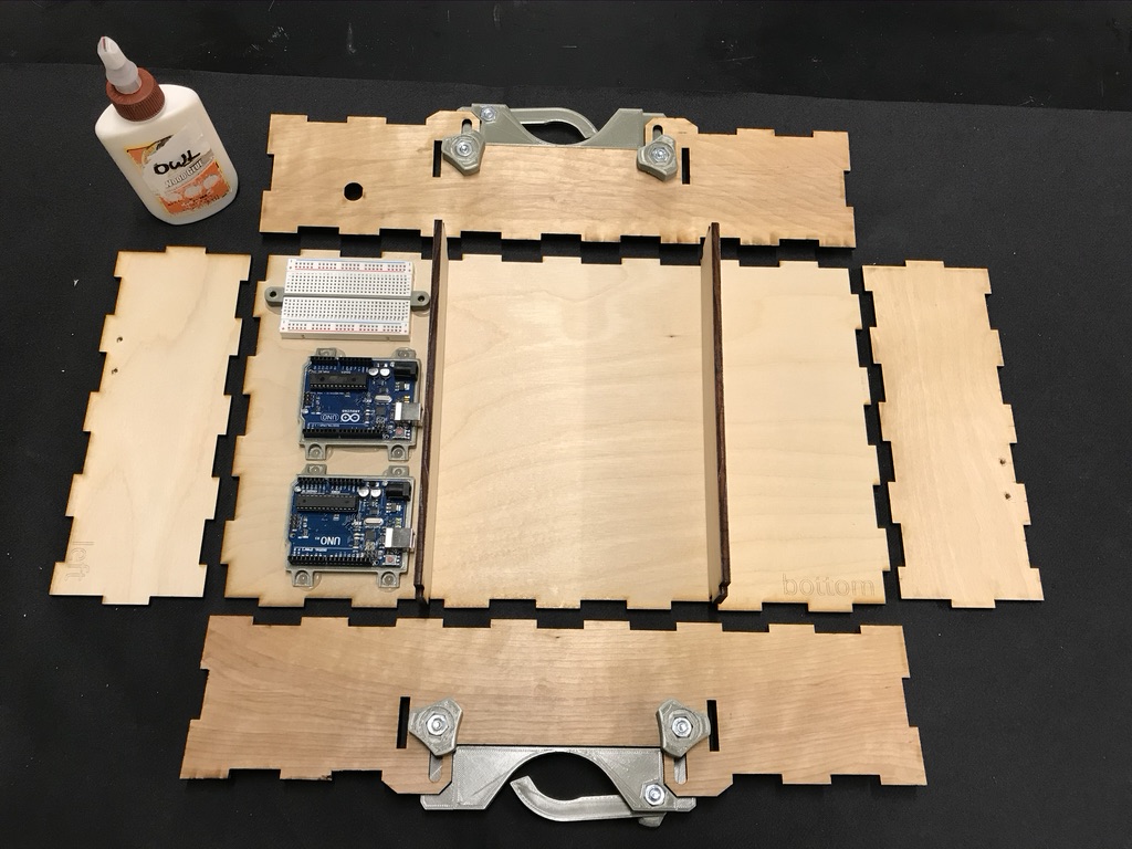
Base assembled |
Place top right panel on box assembly. Do not glue! |
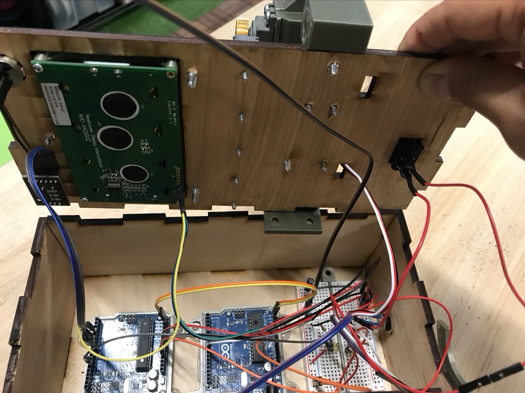
Install and secure power jack with leads soldered on. |
Attach jumper wires to rotary encoder, display, and momentary button. |

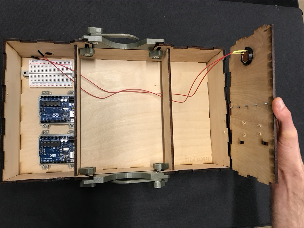

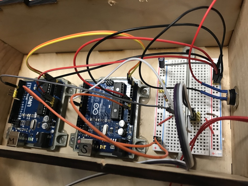
Wire arduinos according to wiring diagram below. |
Connect control assembly according to wiring diagram below and install on box. |
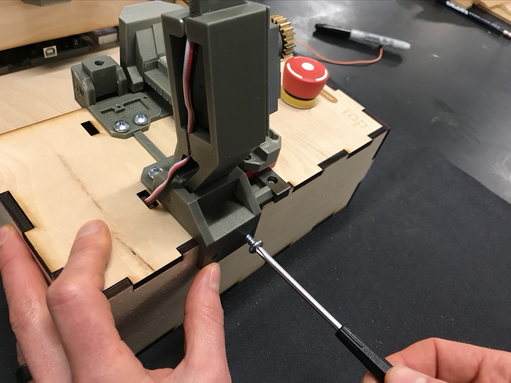
Push motor mount assembly up against linear rail and secure using (5) #8 x 3/4" screws. |
Carefully slide gear rack assembly on linear rail. |


.png)
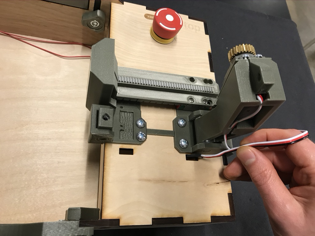
Route servo motor wires through cable pass-through. |
Secure motor mount to box using (2) #8 x 3/4" screws. |
Rotate servo mount arm and observe alignment. If not aligned (shown above) use appropriate shim to center gear to gear rack. Lift arm off of gear rack when finished checking alignment. |

Assembled |
Power on device and install software. |
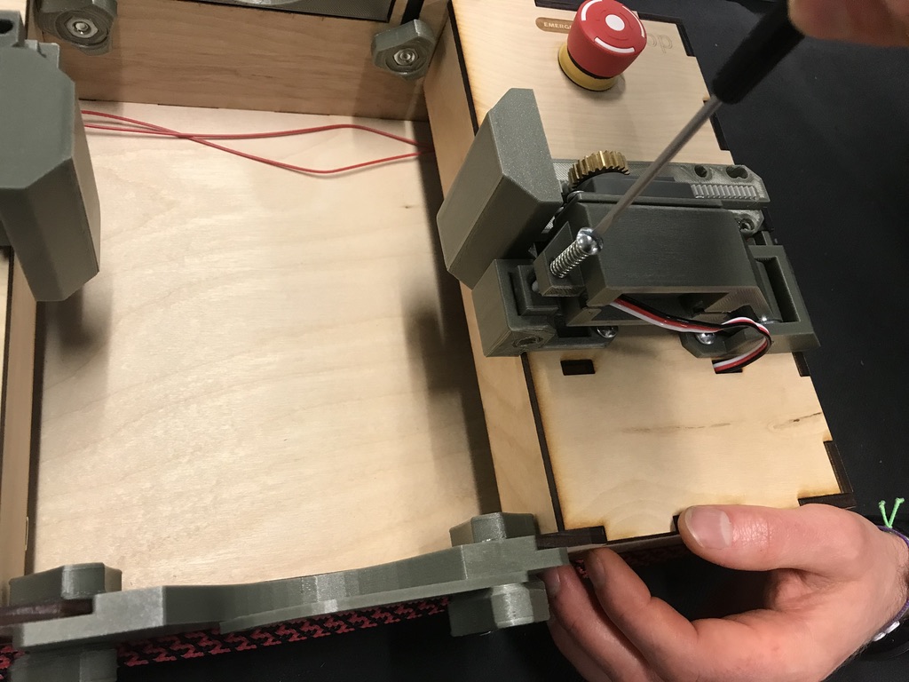
Push gear rack assembly back until it stops. Lower servo mount arm. Insert (1) 10-24 x 1-1/2" bolt inside 1" spring and secure to spring base. |

You will need to make 2 of these for the finished design.
Slide 32P,32T 25 Tooth Spline direct mount gear to servo motor. |
Use screw provided with servo to secure gear to servo. |
Place 2mm servo shim under servo mounting lip. |


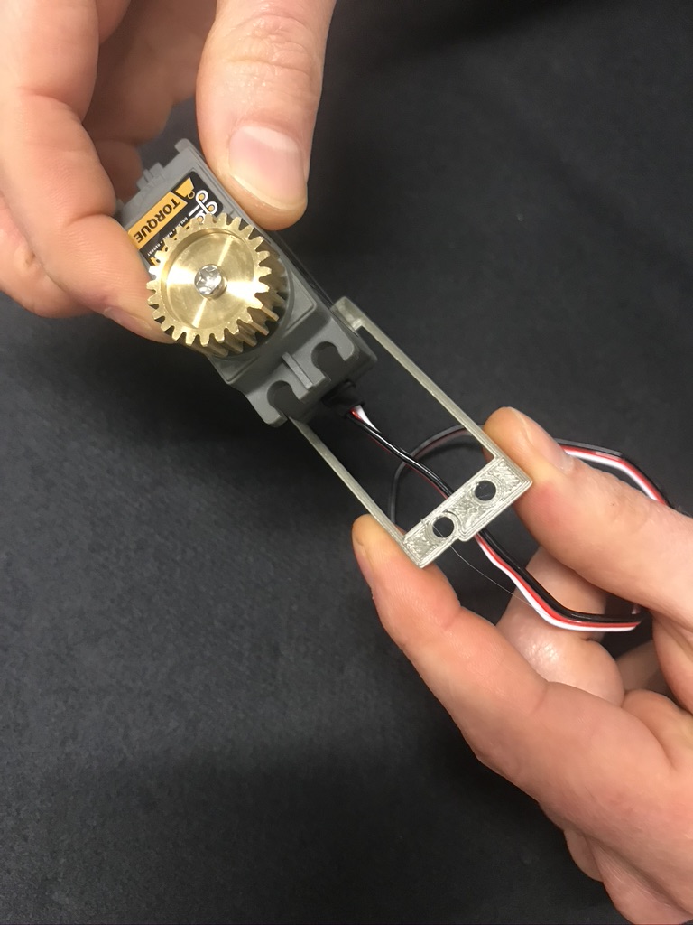
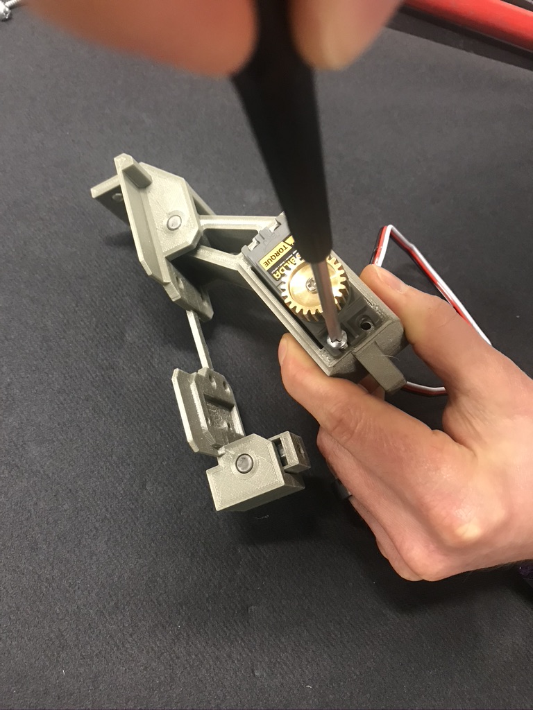
Route wire through servo rotational mount and insert servo. |
Secure with (4) #6 x 1/2" thread-forming screw for plastic. |
You will need to make 2 of these for the finished design.
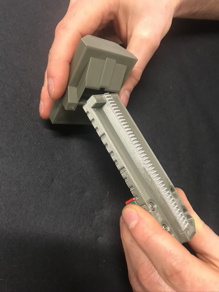
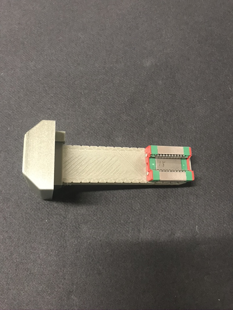
Gear rack assembly. |
Cut gear rack to length and press fit into base. (Use glue if rack slides out easily) |
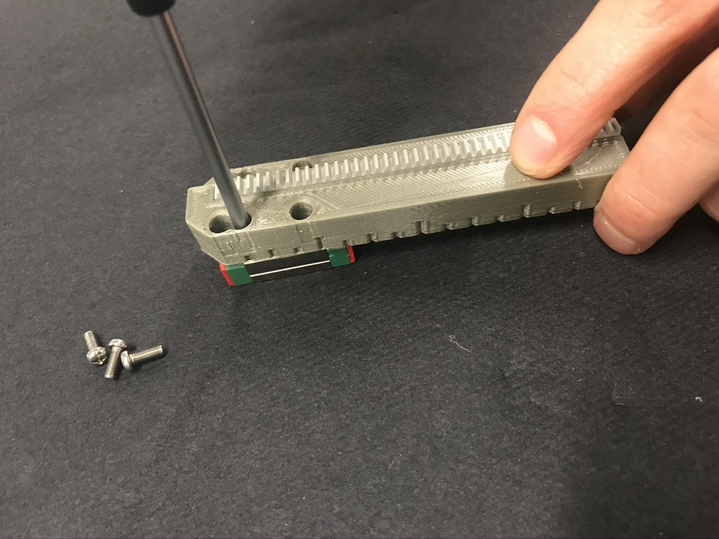
Secure base to MGN12 (or MGN12H) rail block with (4) M3 x 8mm screws. |
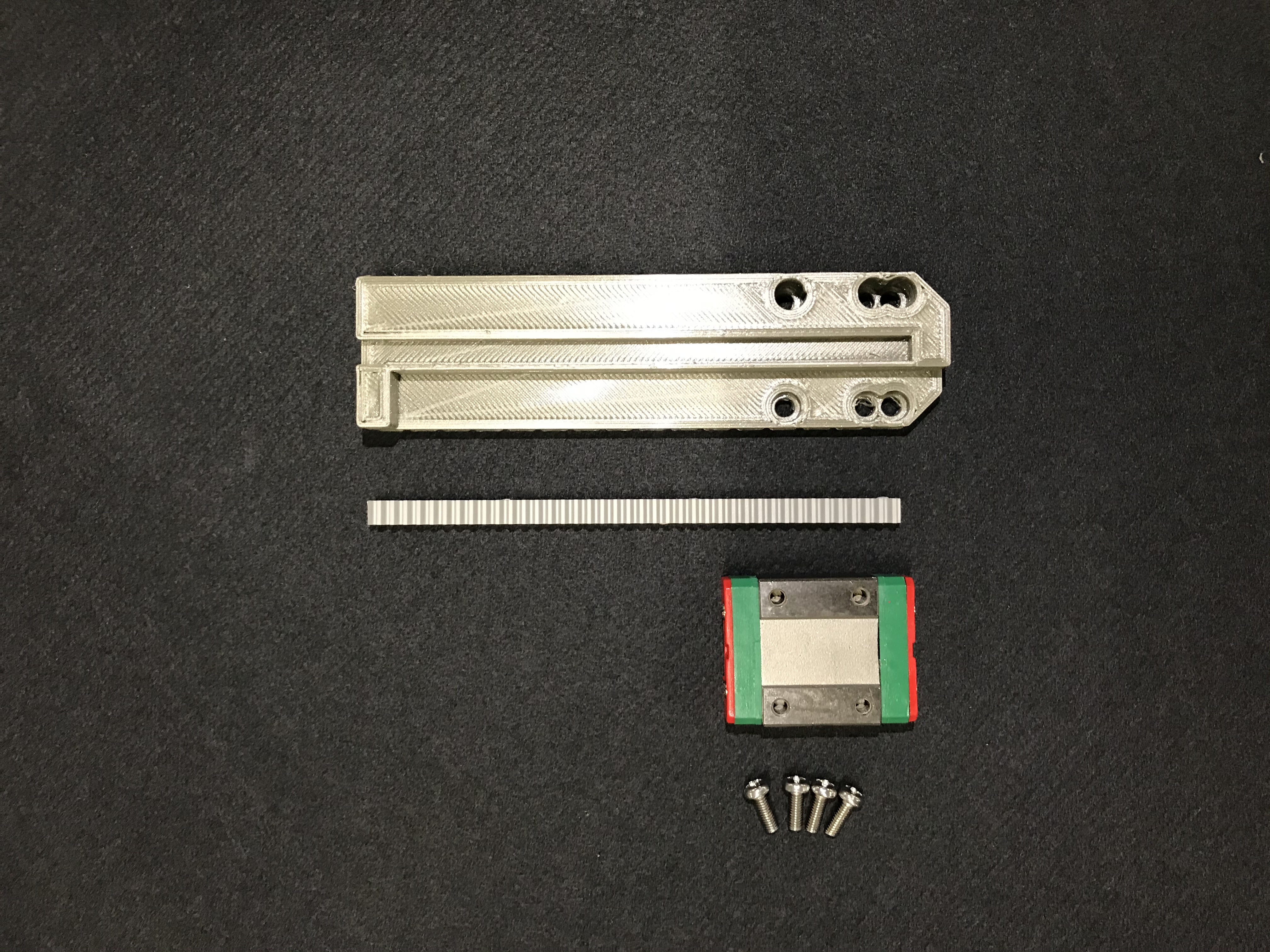
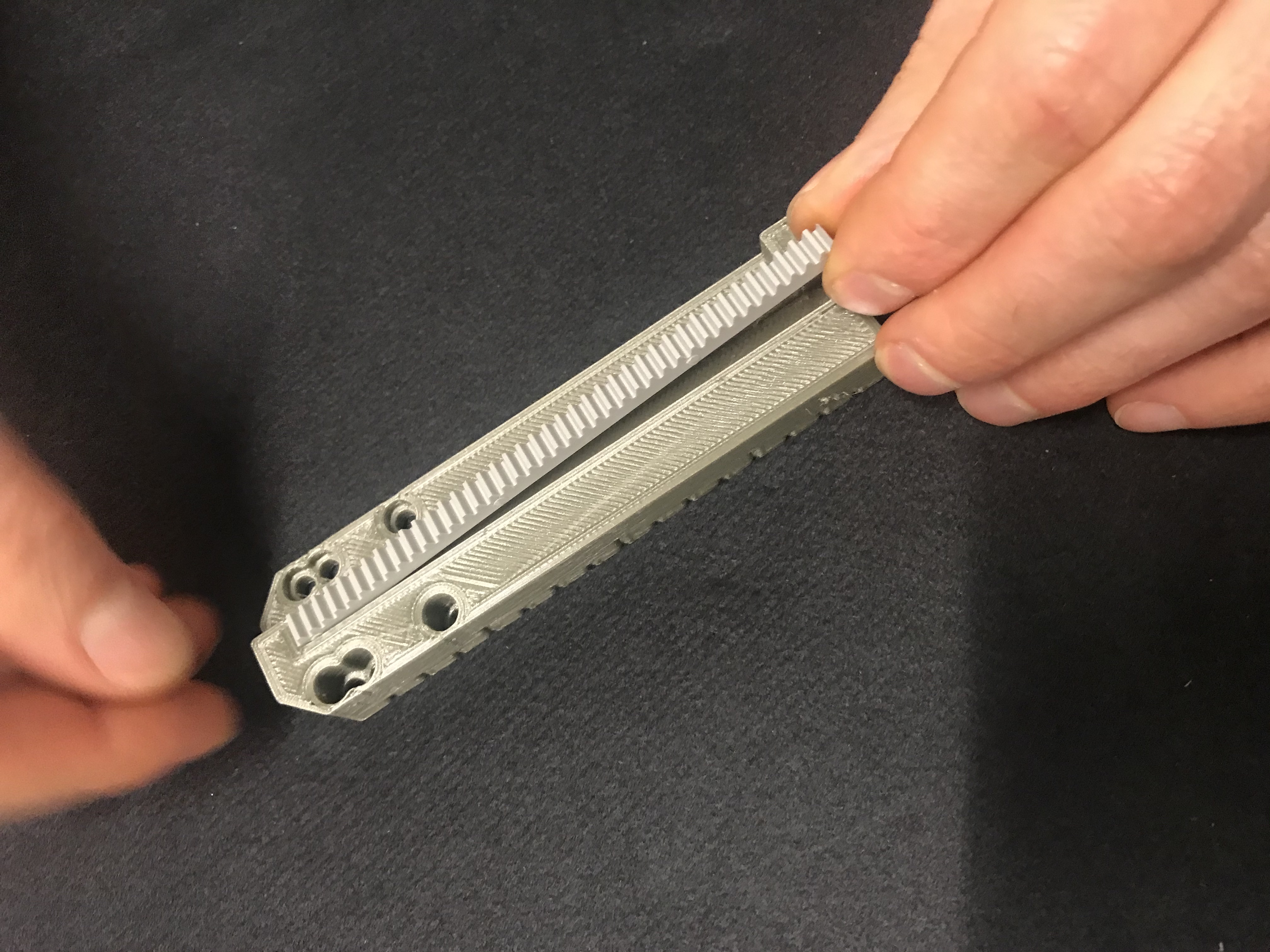
Press bumper to gear rack base. (Use glue if bumper feels loose) |
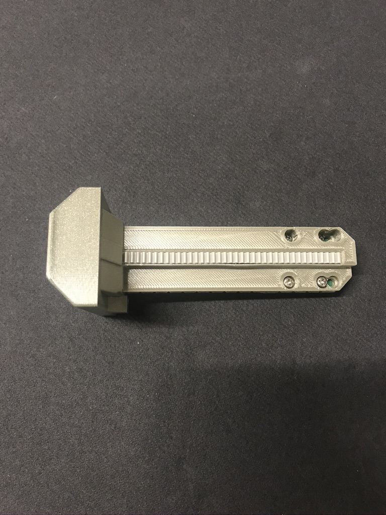
Completed assembly. |
Completed assembly with rail block. |
|
|

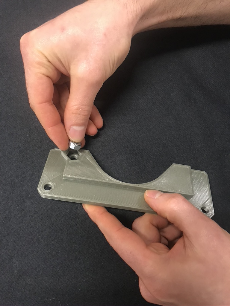
Insert 1/4"-20 nut into BVM support bottom. |
Insert remaining 1/4"-20 bolts and nuts into knobs. |
BVM adjustable mount with fasteners. |


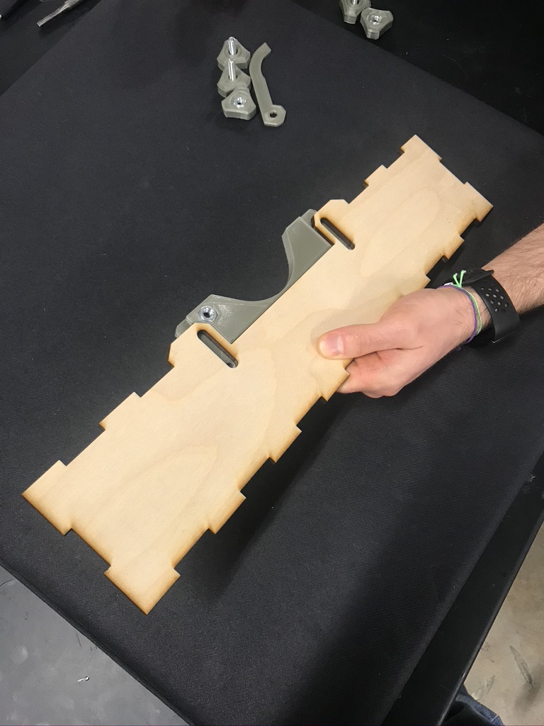
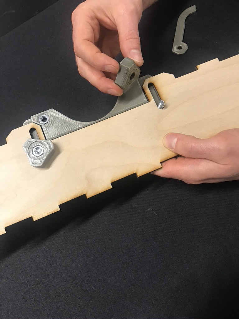
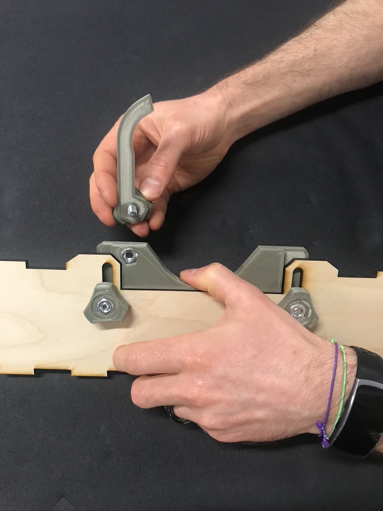
Place BVM support bottom onto wood box - front as shown. |
Use (2) 1/4"-20 x 1-1/2" knobs to secure BVM support bottom to wood box -front. |
Place clamp arm on 1" knob assembly and secure to BVM support bottom. |
The ApolloBVM system uses two coordinated microcontrollers in order to facilitate user input while guaranteeing uninterrupted airflow. The system has a master controller, responsible for managing the display and user input, and a slave controller that actually sends motor commands to the servos. This allows the master controller to operate entirely separately from the slave and ensures that the system is real-time safe. In order to give more clarity about the technical operation of this device, we will outline the operation of each controller separately.
In order to facilitate the various functions of the device, the slave controller operates in 3 distinct states: load, on, and off. While in the ‘load’ state, the slave controller will read ventilation parameters from the master over the I2C bus, generate a new trajectory with these parameters, and turn its state to ‘on’. While in the ‘on’ state, the device will follow the trajectory over and over for infinity. This means that the slave controller will never stop moving the motors unless it receives a command from the master to change its state to ‘stop’. If the master controller were to do so, the device would finish its current cycle and stop moving.
The master controller is mainly tasked with running the user display and sending commands to the slave. Internally, the master switches which panel is currently displaying and manages input from the encoder and buttons. Each panel that the master displays is programmed to follow a different behavior and is modular. This makes it easy to implement panels that behave completely differently and interact with the slave controller on the fly.
For implementation details, please refer to the Github repository where we documented source code.
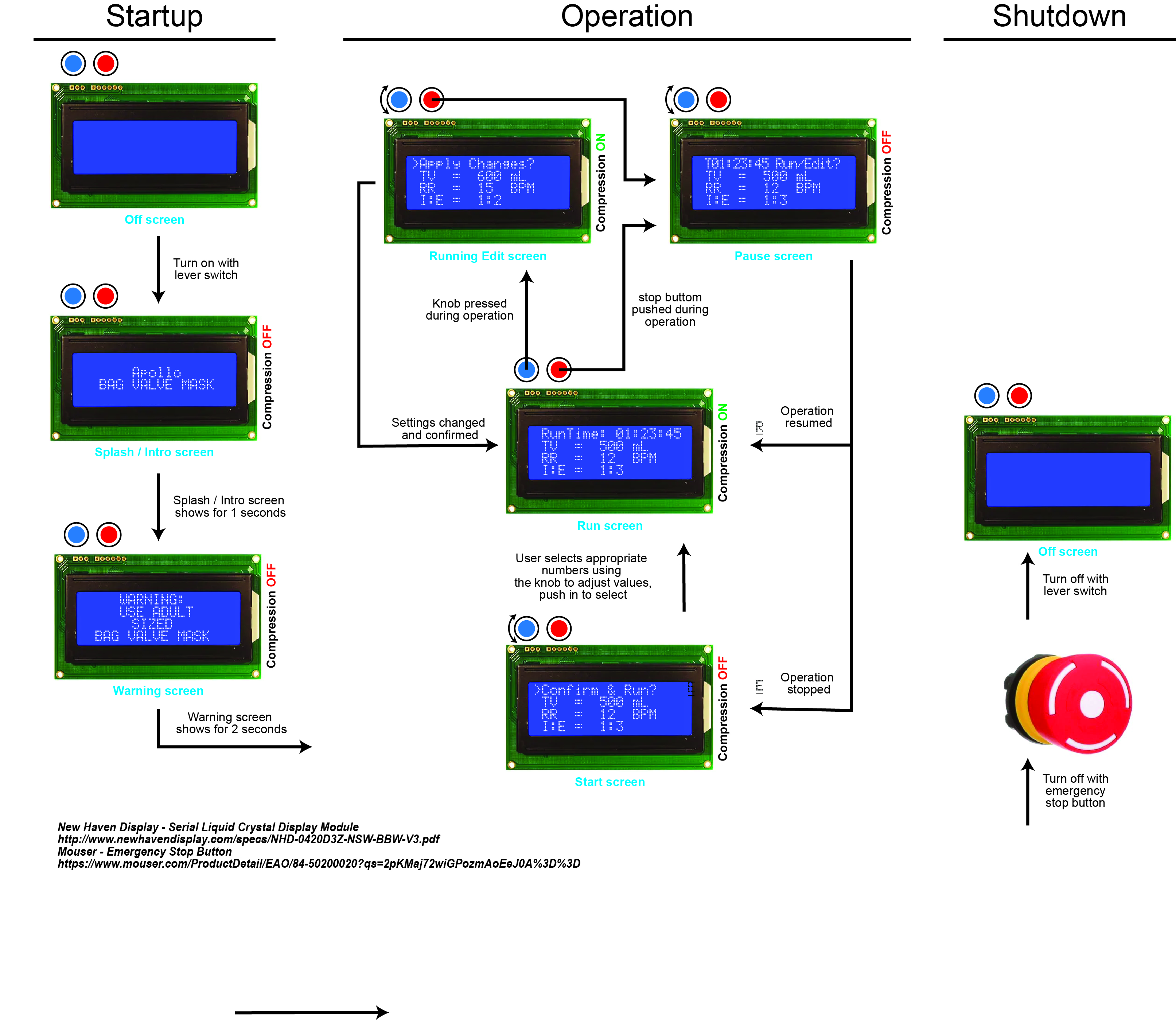
Set up of Ventilation Parameters
All ventilation parameters must be set by the clinical provider caring for the patient. It is suggested to have the patient sedated with neuromuscular blockade for the acute phase of respiratory support. This may be followed by titrated sedation to a RASS score of -2. All patients should be continuously monitored during mechanical ventilation to include pulse oxygenation and also ideally continuous capnometry (end-tidal carbon dioxide -- ETCO2).
The minimum controllable parameters in order to ventilate a patient on ApolloBVM include:
| Parameter | Range | Default |
| Respiratory Rate (breaths/min) | 5-30 | 12 |
| VT (Tidal volume in cc, set at 6-8 cc/kg of ideal body weight) | 300-650 | 500 |
| I:E (Inspiratory time/Expiratory time per cycle) | 1:2 to 1:4 | 1:3 |
| PEEP (Positive end expiratory pressure in cmH20) | 5-20 | 8 |
PEEP Valve or Gauge
Most BVMs include a PEEP valve with an adjustable dial set for 20-40 cmH20. The purpose of this valve is to limit peak airway pressure to the number set on the dial. Ideally, peak airway pressure should be less than 40 cmH20. It will not be possible to measure PEEP with this valve.
Select BVM models include a PEEP valve with a gauge that ranges from 0-60 cmH20. These models allow for calibrated monitoring of PEEP during all portions of the breath cycle.
VT should be adjusted until the desired PEEP value is reached at the end of the breath cycle (8 cm H20 is a reasonable initial target).
With regard to ventilated COVID patients, it is quite likely that the desired PEEP will reach the 10-15 cmH20 range quickly.
Plateau Pressure
On an inspiratory hold of 0.5 seconds (at the end of the inspiratory portion of breath cycle), measured pressure should be <30 cmH20 to minimize ventilator-induced lung injury (VILI).
Emergency stop
There is an emergency shut-off button that turns off the device and allows for manual override and standard use of the BVM. (Version 1)
Supplemental Oxygenation
Most BVMs have a port to blend-in oxygen. Room air is 21% oxygen. Wall or tank-based oxygen is 100% oxygen. The higher the flow rate for ported-in oxygen, the higher the fractional percent of oxygen delivered to the patient. In acute ventilatory support, room air is often sufficient. Appropriate VT and PEEP are the keys to gas exchange.
Viral Filtration
HEPA filters should be placed on the ETT connector and then the filter is connected to the breathing circuit and BVM unit. This allows for all expired air at the point of exit from the mouth to be filtered prior to entering the BVM which contains an open aerosolization port.
Breathing Circuit
The use of a single-line disposable breathing circuit aids in the maintenance of heated and humidified air returning to the patient and also allows for placement of the ApolloBVM at a safe distance from the patient.
Version 1 Phase 1 Testing
Respiratory Bag: Ambu Spur II I:E RATIO: 1:3
Percent Error:
| Respiratory Bag: Unknown I:E RATIO: 1:3
Percent Error:
|
Click HERE to see the Phase 1 testing results.
As updates are developed, they will be posted here.
Contact: apollobvm@rice.edu
ApolloBVM Design team
All design work on the ApolloBVM was done at the Oshman Engineering Design Kitchen at Rice UniversityDanny Blacker - Lead Designer
Dr. Maria Oden - Faculty Mentor
Dr. Matthew Wettergreen - Faculty Mentor
Thomas Herring - Controls Lead
Amy Kavalewitz - Project Manager
Dr. Rohith Malya - Clinical Lead
Fernando Cruz - Engineering Design Technician
Inspired by the 2018-2019 senior design project Team Take A Breather
Legal Notices, Terms, and Conditions.
By using the information provided on this site, you agree to and accept the legal terms and conditions in the ApolloBVM Disclaimer. You should carefully review all of the terms and conditions of the license and disclaimers before using the information provided.
This information is licensed under a Creative Commons Attribution 4.0 International License.
![]()
The ApolloBVM System has not been FDA Approved by the Food and Drug Administration (FDA) or any other governmental or oversight authority.
Several FDA guidance documentation may apply, as well as certain declarations on liability immunity for pandemic countermeasures.
The information is being provided without warranties (expressed and/or implied).
Nothing on this site or in the Information is intended or shall be construed as medical advice.
No other licenses are granted, including for use of any trademarks of Rice or other intellectual property rights beyond the attribution requirements under the license. Attributions shall not be suggestive of endorsement by Rice.
There is no further obligation of Rice to make available clinical data, modifications, or improvements to the ApolloBVM System.
|
